This Greener Corporation Tech Bite presents an introduction and refresher course on flow wrapper cutting and sealing head components. Knowing these components and understanding how they function is important, base knowledge for operators, maintenance personnel, engineers, packaging material suppliers, and others that work to efficiently produce quality packaging.
The following illustrations and descriptions are based on a common cutting and sealing head design. Components and adjustment methods may differ on some wrapper makes and models, but their overall function remains the same.
Shafts
The head includes a lower shaft and an upper shaft.
Bearings and Bearing Blocks
Bearings that support the shafts and allow them to rotate accurately are mounted in the bearing blocks.
Gears
The lower shaft is driven by the packaging machinery. A gear on the lower shaft mates with and drives a gear on the upper shaft. In most cases, the upper gear can be adjusted to spin the upper shaft independently of the lower shaft to ensure proper alignment and phasing of the sealing jaws.
A split, or anti-backlash, gear can be adjusted to remove backlash, or free play, between the gears, which causes misalignment of the sealing jaws.
Sealing Jaws
Lower sealing jaws are mounted on the lower shaft, and upper jaws on the upper shaft.
Sealing jaws should be installed with proper mounting bolts and hardened washers to ensure that they are accurately seated on the shafts and don’t shift out of alignment.
A flow wrapper can utilize one to four, and occasionally more, pairs of sealing jaws, depending on package length and line speed requirements.
Heaters and Thermocouples
For heat seal applications, cartridge heaters and thermocouples are inserted into holes bored in the sealing jaws and are connected to the temperature controller through slip rings or rotary electrical connectors mounted on the end of each shaft.
Clearance Adjustment Rods
On many wrappers clearance adjustment rods are adjusted to set the clearance between the upper and lower shafts when sealing jaws are installed.
Some makes and models use other clearance adjustment methods.
Pressure Springs
On most flow wrappers pressure springs are adjusted and locked to create the pressure required to seal and cut packages.
Some wrappers utilize compression washers to create this pressure.
Anvils and Knives
Anvils are typically installed in the lower sealing jaws. Packaging knives installed in the upper jaws are adjusted with shims or screws to properly contact the opposing anvil and cut the packaging film.
Product Carriers
Product carriers mount on the lower shaft to support packages and keep them on the same horizontal plane as they pass from the infeed belt, through the cutting and sealing head, and onto the discharge belt.
With basic knowledge of the cutting and sealing head assembly on your flow wrappers you can better understand not just the function of individual components, but also how their design and adjustment effect each other and the resulting package quality and productivity.
To learn more about design, setup, and problem-solving for cutting and sealing head components, visit and subscribe to our Technical Resource Blog and contact Greener Corporation.
We provide Integrated Parts and Packaging Machinery Services worldwide.
Tags
Knives and Anvils
Sealing Jaws
Setup and Adjustment
Training
Troubleshooting
Related Posts
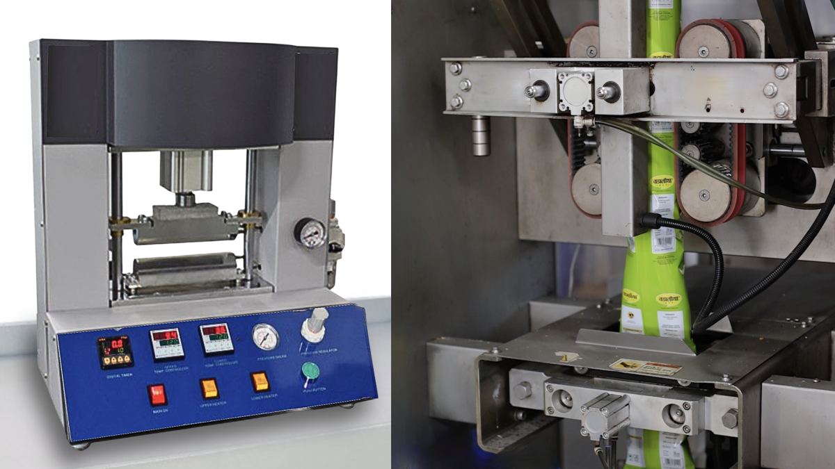
Laboratory & Manufacturing Seal Range: Crucial Distinctions & Their Impact on Package Quality & Machine Speed